DIN 40700 logic gates in CircuiTikZ
07 Nov 2016I am a University student, and at University sometimes I see myself forced into utterly insensible conventions.
Case in point: The electrical engineering module which I currently attend. The convention is to draw logic gates according to a standard which has been abandoned since the 1970s, and it is called “DIN 40700.” The logic gates look generally fairly similar to the currently used US logic gates, but some of them are completely different.
I usually do my homework in LaTeX, so naturally I tried out CircuiTikZ. CircuiTikZ is a LaTeX package for drawing electric circuits, it is possible to use the US logic gates as well as the European ones, but not the old DIN gates, so I wanted to find a way to implement them.
I did, and here you can download the result, with some installation instructions: circuitikz-german-logic. I am most welcome to your issues and pull requests, because I only tested this on one configuration (Arch Linux with TeXLive/XeLaTeX).
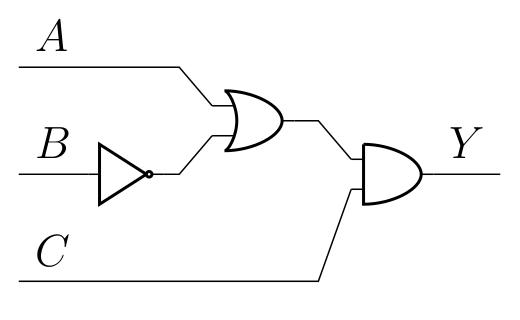
| Before (US gates) | After (DIN 40700 gates) |
|---|---|
 |
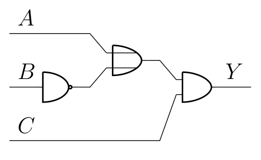 |
Small explanatory note: The leftmost gate is a not gate, the middle gate is an or gate, and the rightmost gate is an and gate, respectively.
How it works
I will focus on the or gate for the sake of this article. It seemed sensible to just take the and gate, and modify it a bit so that it looks like the German or gate.
The and gate is defined in pgfcirctripoles.tex in the lines following the declaration \pgfdeclarelogicport{and}. What we find in the body of the definition are a set of commands for PGF, which is a LaTeX macro package for creating graphics. The layout of the and gate is basically a sequence of moveto, lineto, and curveto commands, and structurally, it consists of:
- The upper input port
- The lower input port
- The output port
- The left part (straight line) of the gate
- The lower part of the curve
- The upper part of the curve
So what we should focus on are the upper (1) and lower (2) input ports. After replacing a couple of variables, the source code reads like this:
\pgfpathmoveto{
    \pgfpoint {res_left}            {input_height*res_up}
}
\pgfpathlineto{
    \pgfpoint {port_width*res_left} {input_height*res_up}
}

\pgfpathmoveto{
    \pgfpoint {res_left}            {input_height*res_down}
}
\pgfpathlineto{
    \pgfpoint {port_width*res_left} {input_height*res_down}
}
After a grep of the source directory, it turns out that port_width is 0.7 and input_height is 0.5, and therefore the thing draws a horizontal line from (-1,0.5) to (-0.7,0.5), and the same line one height unit below again.
I just copied this part, renamed the gate, and modified the code above so that it looks like this:
\pgfpathmoveto{
    \pgfpoint {res_left}            {input_height*res_up}
}
\pgfpathlineto{
    \pgfpoint {0.5*res_right}       {input_height*res_up}
}

\pgfpathmoveto{
    \pgfpoint {res_left}            {input_height*res_down}
}
\pgfpathlineto{
    \pgfpoint {0.5*res_right}       {input_height*res_down}
}
Now it draws a horizontal line from (-1,0.5) to (0.5,0.5), and the same line mirrored to the other side.
The procedure was similar for the not gate, which is basically the US nand gate with only one input instead of two.